W2 - ATTiny85 + Capacitive sensor
ATtiny85 programming jig
I continued soldering pins and wires to complete the programming jig.


Capacitive sensor
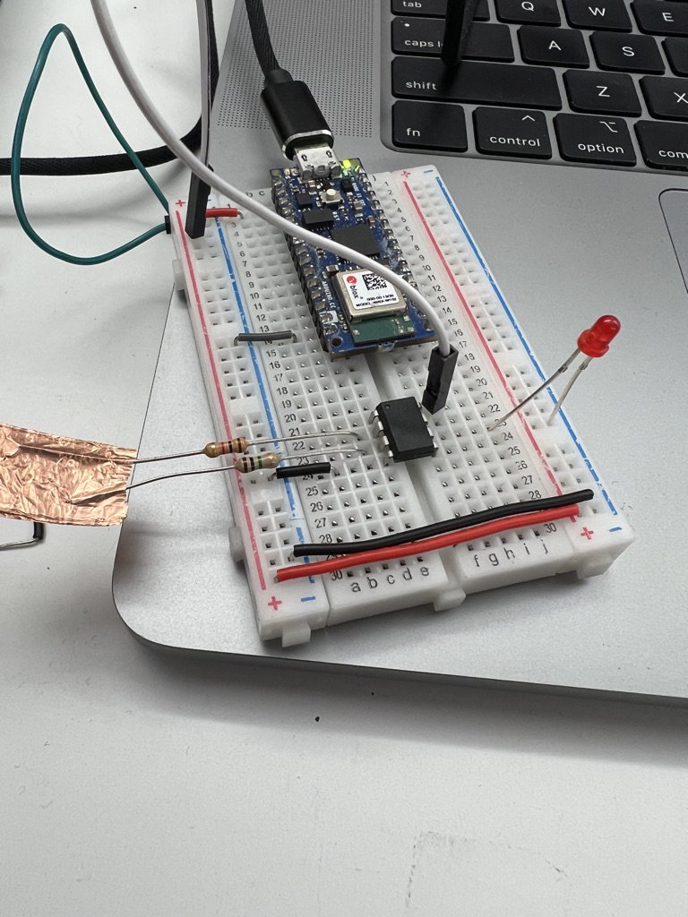
I used the Arduino to supply 3.3V power to the ATTiny85 and the LED.
I connected a 1M resistor to pin 4, a 10k resistor to pin3, and an LED to pin 1.
The two resistors are connected with a segment of copper tape.
Here is the code loaded to ATTiny85:
#include <CapacitiveSensor.h>

CapacitiveSensor   cs_4_3 = CapacitiveSensor(4,3);        // 10M resistor between pins 4 & 2, pin 2 is sensor pin, add a wire and or foil if desired

void setup()
{
   cs_4_3.set_CS_AutocaL_Millis(0xFFFFFFFF);     // turn off autocalibrate on channel 1 - just as an example
   pinMode(1, OUTPUT);
   Serial.begin(9600);
}

void loop()
{
    long start = millis();
    long total1 =  cs_4_3.capacitiveSensor(30);

//    Serial.print(millis() - start);        // check on performance in milliseconds
//    Serial.print("\t");                    // tab character for debug windown spacing
//
//    Serial.println(total1);                  // print sensor output 1
    if ( total1 >99){
      digitalWrite(1, HIGH);   // turn the LED on (HIGH is the voltage level)
    }else{
      digitalWrite(1, LOW);   // turn the LED on (HIGH is the voltage level)
    }

    delay(10);                             // arbitrary delay to limit data to serial port
}
Here is the video: